
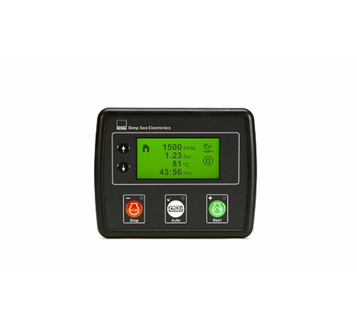

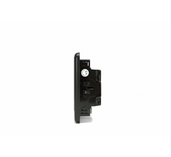
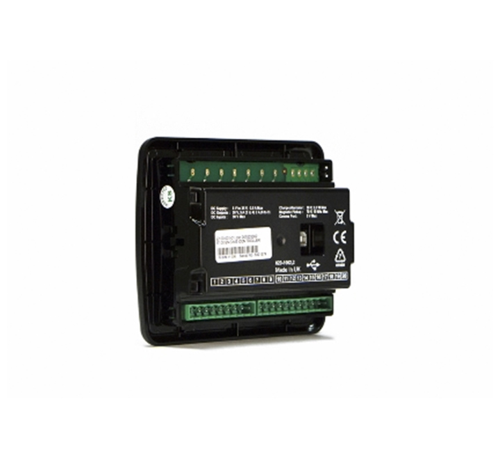

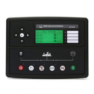
Original DSEE100 | Engine Only Control Module

Limit Stock
140 mm x 113 mm x 43 mm (5.5″ x 4.4″ x 1.7″)
PANEL CUT OUT
118 mm x 92 mm (4.6″ x 3.6″)
PRODUCT VARIANTS
E100-01 – E100 Engine Controller
Call for Quote for international purchases!
$335.99
The M040 is a development kit for the M64X controller range. It allows the user to connect the breakout PCB to a laptop and control unit to assist with application development.
| BRANDS | DSE |
|---|
Technical Specifications
| Key Features | Key Benefits |
| Configurable DC outputs (4). | Provides the option to tailor the operation to meet system demands. |
| Configurable analogue/digital inputs (3). | Provides a comprehensive range of multiple monitoring options. |
| Configurable digital inputs (4). | Provides a comprehensive range of multiple monitoring options. |
| Engine maintenance alarms (3). | Supports efficient maintenance schedules. |
| Fuel and start outputs. | Dedicated outputs for simple connection. |
| Configurable event log (50). | Assists fault finding and operating trends. |
| REngine pre-heat. | Prevents engines from starting when too cold. |
| Engine speed protection. | Protects the engine. |
| Engine hours counter. | Can be used to schedule servicing schedules. |
| Engine run time scheduler. | Allows engine to be run at pre-configured times. |
| Battery voltage monitoring. | Detects if the battery voltage drops. |
| Start on low battery. | Allows engine to be started when connected battery is at low voltage. |
| LCD alarm indication. | Presents alarm status clearly on the front display. |
| Power save mode. | Saves energy. |
| Front panel/PC software configuration. | Flexible configuration for the user. |
Related products
-
Remote Communications & Overview Displays
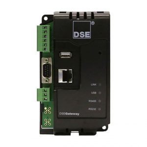
Original DSE892-01 | Simple Network Management Protocol (SNMP) Gateway
 Remote Communications & Overview Displays
Original DSE892-01 | Simple Network Management Protocol (SNMP) Gateway
OVERALL SIZE
85 mm x 149 mm x 51 mm (3.3” x 5.8” x 2.0”)
WEIGHT
0.24kg
PRODUCT VARIANTS
0892-01 – 892 Simple Management Network Protocol (SMNP) GatewayCall for Quote for international purchases!
SKU: DSE892-01 -
Manual & Auto Start Control Modules, Remote Communications & Overview Displays
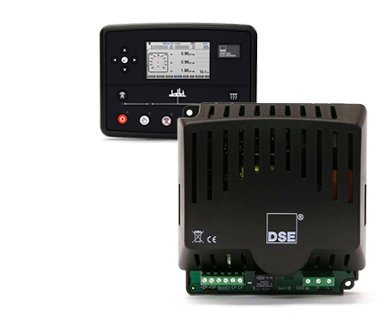
Original DSE7310 MKII | Auto Start Control Module
 Manual & Auto Start Control Modules, Remote Communications & Overview Displays
Original DSE7310 MKII | Auto Start Control Module
OVERALL SIZE
245 mm x 184 mm x 51 mm (9.6″ x 7.2″ x 2.0″)
PANEL CUTOUT SIZE
220 mm x 160 mm (8.7″ x 6.3″)
MAXIMUM PANEL THICKNESS
8.0 mm (0.3″)
PRODUCT VARIANTS
7310-03 MKII Auto start Control Module
7310-33 MKII Auto Start Controller
7310-34 MKII Auto Start Controller with Heated DisplayCall for Quote for international purchases!
SKU: DSE7310 -
Auto Mains (Utility) Failure Control Modules
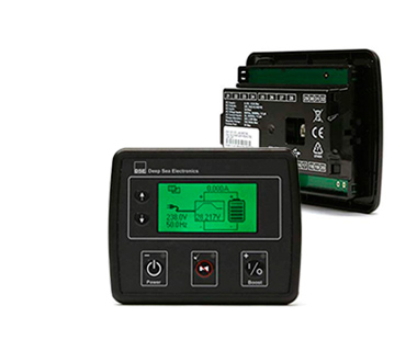
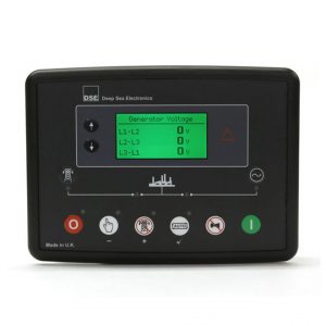
Original DSE6020MKII | Auto Mains (Utility) Control Module | 6020-03
 Auto Mains (Utility) Failure Control Modules
Original DSE6020MKII | Auto Mains (Utility) Control Module | 6020-03
OVERALL SIZE
216 mm x 158 mm x 43 mm (8.5” x 6.2” x 1.5”)
PANEL CUTOUT SIZE
184 mm x 137 mm (7.2″ x 5.3″)
MAXIMUM PANEL THICKNESS
8.0 mm (0.3”)
WEIGHT
0.48kg
PRODUCT VARIANTS
6020-03 – MKII Auto Mains (Utility) Failure Control ModuleCall for Quote for international purchases!
SKU: DSE6020-03 -
Load Sharing & Synchronizing Control Modules
Original DSE8660 MKII | Auto Transfer Switch & Mains (Utility) Control Module
 Load Sharing & Synchronizing Control Modules
Original DSE8660 MKII | Auto Transfer Switch & Mains (Utility) Control Module
OVERALL SIZE
245 mm x 184 mm x 51 mm (9.6″ x 7.2″ x 2.0″)PANEL CUTOUT SIZE
220 mm x 160 mm (8.7″ x 6.3″)MAXIMUM PANEL THICKNESS
8.0 mm (0.3″)WEIGHT
0.88kgPRODUCT VARIANTS
8660-02 – 8660 MKII Auto Transfer Switch & Mains (Utility) Control Module (Ct, Rtc)Call for Quote for international purchases!
SKU: 8660-02